Fundamentals of Insulation Resistance Testing for Electrical Cable Systems
Insulation resistance (IR) testing represents a cornerstone procedure in the predictive and preventative maintenance of electrical systems. This non-destructive test methodology is paramount for assessing the integrity of the dielectric material surrounding conductive elements within cables and a vast array of electrical components. The primary objective is to quantify the electrical resistance offered by the insulation, thereby providing a critical metric of its ability to prevent current leakage, short circuits, and potential catastrophic failures. In an era defined by the proliferation of sophisticated electronics across industries—from aerospace avionics to medical diagnostic equipment—the reliability of the insulating materials that separate potentials is non-negotiable. This article provides a comprehensive examination of IR testing principles, standards, methodologies, and the instrumental role of advanced test equipment such as the LISUN WB2681A Insulation Resistance Tester in ensuring operational safety and longevity.
The Electrochemical Principles Underlying Insulation Degradation
To fully appreciate the necessity of IR testing, one must first understand the mechanisms through which insulation deteriorates. Insulation materials—including polyvinyl chloride (PVC), cross-linked polyethylene (XLPE), rubber, and Teflon—are not perfect dielectrics. Over time, they are subjected to a combination of environmental and operational stresses that compromise their molecular structure. Key degradation factors include thermal cycling, which causes expansion and contraction leading to micro-fractures; moisture ingress, which creates conductive pathways; chemical contamination from oils or solvents; and electrical stress from transient overvoltages or corona discharge.
These factors contribute to a gradual reduction in the material’s resistivity. The insulation resistance value itself is an expression of Ohm’s Law (R = V/I), where a known DC voltage (V) is applied, and the resulting small leakage current (I) is measured. A high resistance value, typically in the megaohm (MΩ) or gigaohm (GΩ) range, indicates healthy insulation with minimal leakage current. A low or declining resistance value signifies that conductive paths have formed within or on the surface of the insulation, increasing the risk of ground faults or phase-to-phase faults. This measurement is not merely a pass/fail checkpoint but a trending tool; by tracking IR values over time, maintenance engineers can predict end-of-life for cable runs and schedule replacements proactively, avoiding unplanned downtime.
Standardized Testing Protocols and Industry-Specific Compliance
The execution and interpretation of IR tests are governed by a framework of international standards to ensure consistency and safety. Key standards include IEEE 43 for rotating machinery, IEEE 95 for DC high-potential testing, and IEC 60364 for low-voltage electrical installations. Perhaps the most universally referenced standard for cable testing is IEC 60502, which specifies test voltages and minimum acceptable insulation resistance values for power cables and their accessories.
Compliance requirements vary significantly by industry, reflecting the criticality of the application. In the aerospace and aviation components sector, standards like DO-160 for environmental testing mandate rigorous IR checks to ensure functionality under extreme pressure and temperature conditions. For medical devices, adherence to IEC 60601-1 is compulsory, requiring stringent insulation testing to protect patients from leakage currents. Similarly, automotive electronics, governed by standards such as ISO 16750, must demonstrate robust insulation integrity to withstand the harsh under-hood environment of vibration, heat, and chemical exposure. Telecommunications equipment, often operating with sensitive low-voltage signals, relies on IR testing to prevent crosstalk and signal degradation caused by insulation breakdown. These standards collectively define parameters such as test voltage levels, stabilization times for readings (often one minute for the “Dielectric Absorption Ratio” or DAR), and minimum acceptable resistance thresholds.
Advanced Methodologies: Beyond Simple Resistance Measurement
A basic spot test—applying voltage for a short duration and recording the resistance—provides a snapshot of insulation health. However, more sophisticated techniques offer deeper diagnostic insights. The most prevalent advanced methodologies are the Dielectric Absorption Ratio (DAR) and the Polarization Index (PI).
The Dielectric Absorption Ratio is calculated by taking the ratio of the insulation resistance measured at 30 seconds to the resistance measured at 60 seconds (R₆₀ₛ / R₃₀ₛ). This ratio is sensitive to moisture and contamination. A low DAR (e.g., below 1.25) often indicates the presence of moisture within the insulation. The Polarization Index is a more extended test, defined as the ratio of the resistance at 10 minutes to the resistance at 1 minute (R₁₀ₘᵢₙ / R₁ₘᵢₙ). The PI is particularly useful for assessing the overall condition of larger machinery windings and long cable runs. A high PI (e.g., above 2.0) suggests clean, dry insulation in good condition, while a low PI (below 1.0) is a strong indicator of excessive moisture, dirt, or aging, necessitating immediate investigation. These time-resistance tests are invaluable for distinguishing between surface leakage (which may be cleanable) and volume conduction through the insulation bulk (which typically indicates irreversible damage).
Instrumentation for Precision: The LISUN WB2681A Insulation Resistance Tester
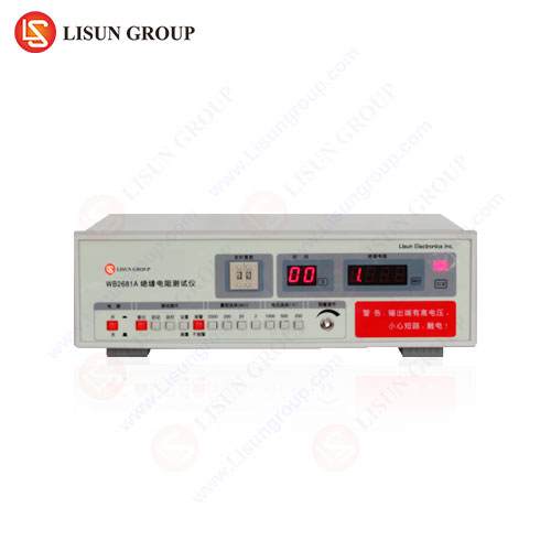
Accurate and reliable IR testing is contingent upon the capabilities of the test instrument. Modern testers must offer a combination of high accuracy, user safety, and operational flexibility. The LISUN WB2681A Insulation Resistance Tester is engineered to meet these demands across a diverse spectrum of industrial applications.
The WB2681A is capable of generating five selectable test voltages: 250V, 500V, 1000V, 2500V, and 5000V DC. This range allows it to be deployed on everything from low-voltage control circuits in office equipment and consumer electronics to medium-voltage power distribution cables in industrial control systems. Its resistance measurement range extends from 0.01 MΩ to 10 TΩ (10,000 GΩ), providing exceptional resolution for both very leaky and highly insulated systems. A key feature is its automatic discharge circuit, which safely dissipates stored capacitive energy from the test specimen after the test is completed, protecting the operator.
The instrument’s design incorporates several competitive advantages. Its digital and analog arc suppression technology minimizes the risk of damage to the device under test from arcing currents. The large LCD display provides clear readouts of resistance, test voltage, leakage current, and test duration simultaneously. For quality assurance in manufacturing environments for household appliances or electrical components like switches and sockets, the WB2681A can be programmed with preset pass/fail thresholds, streamlining the production line testing process. Its robust construction and compliance with international safety standards (e.g., IEC 61010) make it suitable for use in demanding field conditions, such as testing telecommunications backbone cables or lighting fixture installations in industrial facilities.
Table 1: Typical WB2681A Test Voltage Applications
| Test Voltage | Typical Application Examples |
|—|—|
| 250 V DC | Low-voltage control cables, Printed Circuit Boards (PCBs) in consumer electronics, telecommunications data lines. |
| 500 V DC | Household appliance wiring, 120/240V building wiring, office equipment power supplies. |
| 1000 V DC | Industrial control system wiring (e.g., 480V systems), low-voltage power cables (up to 1kV), automotive high-voltage battery cables. |
| 2500 V DC | Medium-voltage power cables (up to 5kV), motor windings, generators. |
| 5000 V DC | High-voltage power cables (up to 35kV), aerospace power distribution systems, utility-grade equipment. |
Practical Application Scenarios Across Industries
The utility of the WB2681A and IR testing, in general, is best illustrated through specific use cases. In the manufacturing of medical devices, such as MRI machines or patient monitors, every cable assembly must be tested to ensure there is no leakage current that could endanger a patient. A 1000V IR test verifies the integrity of the internal wiring before the device is approved for shipment.
Within the automotive electronics sector, the shift towards electric vehicles (EVs) has elevated the importance of IR testing. The high-voltage battery packs and traction motors in an EV operate at several hundred volts. An IR test at 1000V or 2500V is performed on all high-voltage cables and connectors to ensure isolation from the vehicle’s chassis, a critical safety requirement to prevent electrocution.
For lighting fixtures, particularly those used in hazardous locations or outdoor environments, IR testing confirms that the insulation between the live parts and the fixture’s grounded metal housing can withstand humid conditions. A failing IR test on a new batch of fixtures would indicate a manufacturing defect in the potting compound or cable entry seals.
In the realm of aerospace, cables running through an aircraft are subject to constant vibration and wide temperature fluctuations. Periodic IR testing as part of a scheduled maintenance check can detect insulation brittleness or cracking before it leads to a system failure. The ability of the WB2681A to perform PI tests is especially valuable here for assessing the overall health of long, complex wiring harnesses.
Interpreting Test Data and Establishing a Maintenance Baseline
A single IR measurement has limited value without context. The most effective maintenance programs establish a baseline measurement for each cable circuit or piece of equipment when it is new and installed correctly. Subsequent periodic tests are then compared against this baseline. Industry best practices, such as those outlined in the ANSI/NETA MTS-2019 standard, often recommend trending the insulation resistance over time. A consistent, gradual decline suggests normal aging, while a sudden, sharp drop is a definitive red flag indicating acute damage or contamination.
Environmental conditions, particularly temperature and humidity, significantly influence readings. It is a standard practice to correct measured IR values to a base temperature (e.g., 40°C) using standardized correction factors to allow for accurate period-to-period comparison. Sophisticated testers aid in this process by recording environmental data alongside the resistance measurement. The ultimate goal is to move from reactive repairs to predictive maintenance, where components are serviced or replaced during planned outages, thereby maximizing system availability and safety.
Frequently Asked Questions (FAQ)
Q1: What is the primary safety consideration when performing an IR test with an instrument like the WB2681A?
The paramount safety rule is to ensure the circuit under test is completely de-energized, isolated, and grounded before connecting the tester. The WB2681A applies high DC voltages, which can be lethal. Always follow lockout/tagout (LOTO) procedures. After testing, the instrument’s automatic discharge function is critical, but it is still essential to verify the circuit is discharged using a reliable voltage detector before disconnecting the test leads.
Q2: How do I select the appropriate test voltage for a specific cable?
The test voltage should be high enough to stress the insulation meaningfully without causing damage. A common rule of thumb is to use a voltage equal to the cable’s rated operating voltage. For higher-voltage systems, standards provide specific guidelines; for instance, testing a 5kV cable might involve a 5kV or 10kV DC test. For low-voltage systems (e.g., 600V and below), 500V or 1000V is typical. Refer to applicable standards like IEC 60502 or manufacturer specifications for precise requirements.
Q3: Why might an IR test yield a “good” reading one day and a “bad” reading the next on the same cable?
Significant fluctuations in IR readings are often attributable to environmental changes. Moisture is the most common culprit. A cable that tests fine on a dry day may show a very low resistance on a humid or rainy day if moisture has penetrated the termination points or the cable jacket. Contamination from dust, oil, or salt can also create temporary leakage paths that are washed away or disturbed, leading to variable readings.
Q4: Can the WB2681A be used to test the insulation of a semiconductor device or an electronic component?
No, it is not recommended. Insulation resistance testers apply high voltages that can easily destroy the delicate oxide layers within semiconductors, integrated circuits, and many capacitors. These components require specialized low-voltage leakage testers. IR testers are designed for passive insulation systems like cable dielectrics, motor windings, and busbar insulation.
Q5: What does a Polarization Index (PI) value of less than 1.0 indicate?
A PI below 1.0 is a critical warning sign. It means the insulation resistance decreased over the 10-minute test period. This phenomenon typically occurs when the insulation is heavily contaminated or wet. The absorption current, which normally decreases over time, is overwhelmed by an increasing conduction current through the moisture or contaminants. Such a result warrants immediate corrective action, such as cleaning or drying the equipment, and may indicate that the insulation requires replacement.


