Fundamental Principles of Insulation Resistance Measurement
The operational integrity and safety of electrical systems are fundamentally contingent upon the condition of their insulation. Insulation resistance (IR) measurement serves as the primary diagnostic technique for assessing the quality of this dielectric barrier. A Megger, a portmanteau of “megohm meter,” is a specialized instrument designed to apply a high direct current (DC) voltage to an electrical component or system and measure the resultant leakage current flowing through its insulation. This measurement is then used to calculate the insulation resistance value, expressed in megohms (MΩ), according to Ohm’s Law (R = V/I). A high resistance value indicates robust, healthy insulation capable of effectively containing current within its intended conductors. Conversely, a low resistance value signifies degradation, contamination, or physical damage, which can lead to current leakage, short circuits, equipment failure, and significant safety hazards including electrical shock and fire.
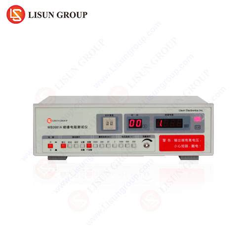
The testing principle relies on applying a stress voltage that is significantly higher than the system’s normal operating voltage. This practice, often standardized at 500 V DC for low-voltage systems or 1000 V DC, 2500 V DC, and even 5000 V DC for medium and high-voltage apparatus, is designed to detect incipient faults that may not be apparent under standard operating conditions. The applied voltage can reveal weaknesses such as moisture ingress, carbon tracking, brittleness from thermal aging, or contamination from dust and oils. Modern insulation resistance testers, such as the LISUN WB2681A, have evolved from traditional hand-cranked models to sophisticated electronic devices capable of performing a suite of tests, including Dielectric Absorption Ratio (DAR) and Polarization Index (PI), which provide deeper insights into the condition of the insulation material over time.
Critical Applications in Electrical System Commissioning and Installation
The initial deployment of any electrical system necessitates rigorous validation prior to energization. The use of a Megger during the commissioning phase is a non-negotiable step to verify the integrity of new installations and ensure compliance with international standards such as IEC 60364-6. During this phase, the primary objective is to confirm that all wiring, from the main distribution panels to final circuits, possesses insulation resistance values that exceed the minimum thresholds stipulated by safety codes.
For new cable installations, a Megger is employed to test between phase conductors, between each phase conductor and earth (ground), and between the neutral and earth. This comprehensive testing regimen identifies installation damage, such as insulation nicks caused during cable pulling, poor terminations, or penetration of moisture into conduits. In industrial control systems, for instance, every motor circuit, including the windings of the motor itself and the associated control wiring, must be tested to ensure there are no ground faults that could cause immediate failure upon startup. The LISUN WB2681A Insulation Resistance Tester, with its selectable test voltages of 50V, 100V, 250V, 500V, and 1000V, is exceptionally suited for this application, allowing technicians to apply the appropriate voltage stress for systems of varying ratings, from 24V control circuits to 600V power distribution systems. Its ability to measure resistance up to 10 TΩ provides a wide dynamic range, ensuring accurate readings even on high-quality, new installations.
Proactive Maintenance Regimes for Predictive Failure Analysis
Reactive maintenance, where repairs are conducted only after a failure has occurred, is a costly and inefficient strategy for managing electrical assets. A far more sophisticated approach involves the integration of Megger testing into a scheduled, proactive maintenance program. The objective is to trend the insulation resistance values of critical equipment over time, enabling the prediction of failure before a catastrophic event transpires.
Electrical rotating machinery, such as motors and generators, are prime candidates for such predictive analysis. The insulation on motor windings is subject to thermal cycling, vibration, and contamination. A gradual, consistent decline in IR values over successive quarterly or semi-annual tests is a clear indicator of ongoing insulation degradation. A more pronounced drop often signals an acute issue, such as moisture absorption or the presence of conductive contaminants. The Polarization Index (PI) test, a feature of advanced testers like the WB2681A, is particularly valuable here. The PI is the ratio of the insulation resistance measured after 10 minutes of applied voltage to the resistance measured after 1 minute. A PI value below 1.0 indicates severely compromised insulation, potentially soaked with moisture, while a value above 2.0 is generally considered healthy for most motor classes. This time-resolved measurement helps negate the effects of surface moisture and provides a more accurate assessment of the bulk insulation’s condition. This methodology is directly applicable to the windings of transformers, solenoids in automotive electronics, and power supplies within telecommunications equipment.
Diagnostic Protocols for Fault Location and System Troubleshooting
When an electrical circuit trips a ground-fault protector or a piece of equipment fails unexpectedly, a Megger is an indispensable tool for systematic fault location. The process involves a methodical isolation of circuit segments to pinpoint the exact location of the insulation breakdown. For example, in a faulted lighting circuit within a commercial building, a technician would first isolate the circuit at the distribution board and perform an IR test on the entire circuit. If a low resistance reading is obtained, the circuit is then segmented—disconnecting fixtures and isolating cable runs—retesting each segment until the faulty section is identified. This could be a damaged cable, a faulty ballast in a fluorescent fixture, or moisture within a socket.
In complex systems like aircraft avionics or medical imaging devices, where reliability is paramount, this diagnostic capability is critical. A sporadic fault in an industrial control panel can be traced to a specific sensor or actuator cable whose insulation has been compromised by abrasion, chemical exposure, or excessive heat. The LISUN WB2681A enhances this diagnostic process with its robust construction and clear digital display, which shows real-time resistance values and test parameters, allowing for quick and confident decision-making in the field.
Compliance Verification with International Safety and Quality Standards
Manufacturers and service providers across all electronics-dependent industries are bound by a framework of international standards that mandate specific electrical safety tests. Insulation resistance testing is a cornerstone of these requirements. Standards such as IEC 60601 for medical devices, UL 60950 for information technology equipment, and ISO 26262 for automotive functional safety all include stringent provisions for dielectric strength and insulation integrity.
For a manufacturer of household appliances, every product leaving the assembly line must pass a dielectric withstand test, which is often preceded by an insulation resistance check. A test voltage, typically 500V DC for a 230V appliance, is applied between the live parts and the accessible conductive parts. The WB2681A, with its programmable test voltage and pass/fail judgment capability, can be integrated into automated production test stations to perform this verification rapidly and reliably. Similarly, for aerospace components, testing to standards like DO-160 requires verification that insulation can withstand harsh environmental conditions, including wide temperature and humidity swings. The data logging functionality of modern Meggers provides the necessary audit trail to demonstrate compliance to regulatory bodies and customers.
The LISUN WB2681A Insulation Resistance Tester: Technical Specifications and Application Versatility
The LISUN WB2681A represents a contemporary solution for the demanding requirements of insulation resistance testing across diverse industries. Its design incorporates precision, user safety, and operational flexibility.
Key Specifications:
- Test Voltages: 50 V, 100 V, 250 V, 500 V, 1000 V DC.
- Insulation Resistance Range: 0.01 MΩ to 10 TΩ.
- Measurement Accuracy: ± (3% + 5 digits).
- Short Circuit Current: Approx. 1.8 mA.
- Timer Range: 1 second to 99 minutes.
Industry Use Cases and Competitive Advantages:
In the consumer electronics and office equipment sector, the WB2681A’s low voltage test options (50V, 100V) are ideal for testing low-power printed circuit boards (PCBs), switch-mode power supplies, and internal wiring without risking damage to sensitive semiconductor components. Its high accuracy at lower resistance values ensures reliable detection of even minor insulation flaws.
For automotive electronics manufacturers, testing wiring harnesses, connectors, and electronic control units (ECUs) is critical. The tester’s rugged design and ability to perform consistent, repeatable measurements make it suitable for both R&D and quality control environments. The programmable timer allows for standardized test durations, ensuring every unit is tested under identical conditions.
Within the lighting fixtures industry, particularly with LED drivers and high-bay industrial lighting, the 1000V test capability is essential for verifying the isolation between primary and secondary circuits, a key safety requirement. The clear, backlit LCD display ensures readability in dimly lit production or maintenance areas.
The instrument’s competitive advantage lies in its combination of a wide measurement range, multiple safety features (including automatic discharge of capacitive loads after testing), and a user interface designed for efficiency. This makes it a versatile tool, equally capable in a high-volume manufacturing setting for electrical components like switches and sockets, and in the field for troubleshooting cable and wiring systems in telecommunications central offices.
Advanced Testing Methodologies: DAR and PI for Material Condition Assessment
Beyond simple spot insulation tests, advanced methodologies provide a deeper diagnostic of insulation health. The Dielectric Absorption Ratio (DAR) is the ratio of a 60-second IR reading to a 30-second reading. It is particularly sensitive to moisture and contamination. The Polarization Index (PI), as previously mentioned, is the ratio of a 10-minute reading to a 1-minute reading. These tests are based on the phenomenon of dielectric absorption, where a good, dry insulation material will “charge” over time, causing the measured resistance to increase. A poor or wet insulation will show little to no increase.
These tests are indispensable for assessing large apparatus with extensive insulation, such as high-voltage generators, power transformers, and long-run power cables in industrial complexes. The LISUN WB2681A automates these tests, performing the timed measurements and calculating the ratios internally, thereby eliminating operator timing errors and simplifying the interpretation of results for maintenance engineers.
FAQ Section
Q1: What is the minimum acceptable insulation resistance value for a 400V industrial motor?
There is no single universal value, as it depends on the motor’s specifications and applicable standards. However, a common rule of thumb is a minimum of 1 MΩ per 1000V of operating voltage, plus 1 MΩ. For a 400V motor, this would suggest a minimum of approximately 1.4 MΩ at operating temperature. A more rigorous approach is to consult the manufacturer’s data and trend historical readings; a value that shows a consistent downward trend is a more significant concern than a stable value that is slightly below a generic guideline.
Q2: Why must capacitive loads be discharged after an insulation resistance test, and does the WB2681A handle this?
During an IR test, the insulation acts as a dielectric, causing the system to behave like a capacitor and store a significant electrical charge. This stored energy presents a severe shock hazard. The LISUN WB2681A incorporates an automatic discharge circuit that safely discharges the load upon completion of a test or if the test is aborted, protecting the operator.
Q3: Can the WB2681A be used to test the insulation of live circuits?
No. Insulation resistance testing must only be performed on de-energized, isolated, and locked-out circuits. Applying a high DC voltage from a Megger to a live circuit will damage the tester and poses an extreme safety risk. Always verify the circuit is de-energized using a certified voltage detector before connecting the Megger.
Q4: How does temperature affect insulation resistance readings?
Insulation resistance has a strong inverse correlation with temperature. As temperature increases, resistance decreases exponentially. For accurate trending, readings should be corrected to a standard base temperature (e.g., 40°C) using published correction factors for the specific insulation class. Comparisons between readings taken at vastly different temperatures can be misleading.


