Fundamentals of Insulation Resistance Measurement
Insulation resistance (IR) testing is a fundamental predictive maintenance and quality control procedure designed to assess the integrity of dielectric materials within electrical systems and components. The core principle involves the application of a high, stable DC voltage—significantly higher than normal operating voltage—across the insulation barrier. This voltage stresses the dielectric, causing a minute, measurable current to flow. This current, known as the leakage current, is the summation of three distinct components: the capacitive charging current, which surges initially and then decays to zero; the absorption current, which decays more slowly as the dielectric material polarizes; and the conduction or leakage current, which remains steady and is the primary indicator of insulation quality. The insulation resistance is then calculated using Ohm’s Law (R = V / I), where R is the resistance in ohms (Ω), V is the applied test voltage, and I is the total measured leakage current.
A high IR value indicates robust insulation with few conductive paths, while a low value signifies degradation, contamination, moisture ingress, or physical damage that could lead to premature failure, short circuits, or electric shock hazards. Standardized tests such as the Dielectric Withstanding Voltage (DWV) or High Potential (HiPot) test are often complemented by IR measurement to provide a comprehensive assessment of a component’s dielectric strength and overall safety.
Critical Parameters for Insulation Tester Selection
Selecting an appropriate insulation resistance tester is a multifaceted decision that extends beyond mere voltage output. A systematic evaluation of the following parameters is essential to align the instrument with its intended applications.
Test Voltage Range and Stability: The available test voltages must correspond to industry standards and the operational stresses the Device Under Test (DUT) will encounter. Common standardized voltages include 50V, 100V, 250V, 500V, 1000V, 2500V, and 5000V. For testing low-voltage equipment like printed circuit boards (PCBs) or telecommunications equipment, 50V to 500V may suffice. Conversely, assessing high-voltage apparatus such as industrial motor windings, power cables, or aviation components necessitates ranges up to 5000V or 10,000V. Voltage stability is paramount; the output must remain constant despite fluctuations in load resistance or input power to ensure accurate and repeatable measurements.
Measurement Range and Accuracy: The instrument’s resistance measurement range must be sufficiently wide to capture both the very low leakage of new, high-quality insulation and the higher leakage of aged or faulty systems. High-performance testers typically offer ranges from several kilo-ohms (kΩ) up to tens of tera-ohms (TΩ). Accuracy, usually expressed as a percentage of the reading plus a number of counts, is critical for reliable data. An accuracy specification of ±(5% + 5) is suitable for field maintenance, while laboratory-grade quality control demands tighter tolerances, such as ±(3% + 2).
Additional Testing Functions: Modern testers often integrate multiple functionalities into a single instrument. Common additions include AC/DC voltage measurement, continuity testing (with a high-current option for testing bonds and connections), and ground bond testing. This convergence enhances operational efficiency by eliminating the need for multiple devices.
Safety Compliance and Design Features: Safety is non-negotiable. Instruments must be certified to international standards such as IEC 61010-1 (Safety requirements for electrical equipment for measurement, control, and laboratory use). Key design features include robust over-voltage and over-current protection for the instrument and the operator, secure test lead connections, and clear warning indicators. A well-designed guard terminal is essential for mitigating the effects of surface leakage currents on the measurement, which is crucial for obtaining accurate results in humid environments or on contaminated surfaces.
Data Logging and Connectivity: For audit trails, trend analysis, and quality assurance documentation, the ability to record and export test data is indispensable. Integrated memory, real-time clock stamping, and connectivity options like USB, Bluetooth, or Wi-Fi allow for seamless transfer of results to computer-based maintenance management systems (CMMS) or laboratory information management systems (LIMS).
The WB2681A Insulation Resistance Tester: A Technical Overview
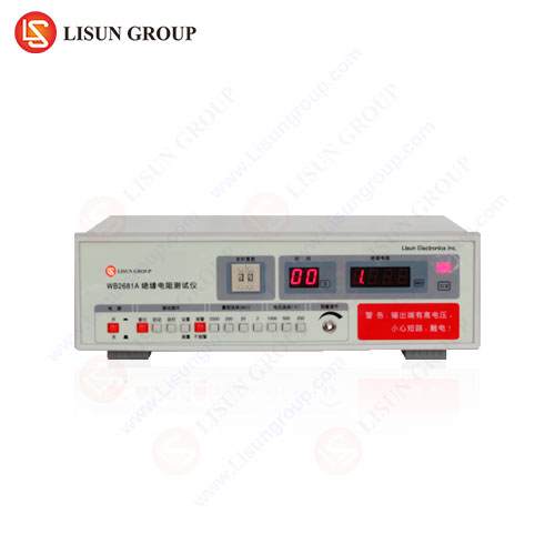
The LISUN WB2681A represents a sophisticated class of insulation resistance testers engineered for rigorous laboratory and production line environments. It is designed to meet the exacting demands of international safety standards, including those for household appliances (IEC 60335), information technology equipment (IEC 60950), and medical devices (IEC 60601). Its design philosophy centers on providing high accuracy, operational safety, and versatile functionality.
Key Specifications and Testing Principles: The WB2681A generates a selectable, stable DC test voltage across a wide range, typically from 50V to 1000V or 50V to 2500V, depending on the model. This voltage is applied to the DUT, and the instrument’s precision circuitry measures the resultant leakage current, calculating and displaying the insulation resistance value on a high-resolution digital display. Its measurement range often extends up to 200 GΩ or 400 GΩ with high accuracy, ensuring it can characterize both moderately insulating and highly insulating materials.
A critical feature is its programmable test sequence. Operators can preset the test voltage, ramp time (the time taken to reach the full test voltage), dwell time (the duration the voltage is applied), and discharge time. This programmability is vital for standardizing test procedures, ensuring consistency, and protecting sensitive components from voltage transients. The instrument automatically discharges stored capacitive energy from the DUT after a test, a crucial safety function.
Industry Use Cases and Application: The WB2681A’s precision makes it suitable for a vast array of industries. In the manufacturing of household appliances and consumer electronics, it is used for mandatory safety testing of power supplies, internal wiring, and motor insulation. Automotive electronics suppliers employ it to validate the insulation integrity of battery management systems (BMS) for electric vehicles, charging ports, and high-voltage cabling. Within medical device manufacturing, it is indispensable for testing patient-isolated circuits in equipment like dialysis machines and MRI scanners to ensure absolute patient safety. Aerospace and aviation component manufacturers use such testers to verify the insulation of critical flight system wiring and connectors, where failure is not an option. Furthermore, producers of electrical components such as switches, sockets, and lighting fixtures rely on it for quality control, ensuring products meet safety agency certifications before market release.
Competitive Advantages: The WB2681A’s advantages are rooted in its robust design and advanced feature set. Its high accuracy and resolution provide confident pass/fail decisions. Programmable test sequences enhance repeatability and throughput on production lines. Comprehensive safety features, including arc and short-circuit detection, protect both the operator and valuable DUTs. Finally, its ability to interface with PC software for data management aligns with modern quality control and traceability requirements, offering a significant advantage over basic, non-connected testers.
Matching Tester Specifications to Industry Applications
The application dictates the instrument’s required specifications. A mismatch can lead to inadequate testing or unnecessary capital expenditure.
Electrical and Electronic Equipment / Office Equipment: For testing PCBs, power supplies, and internal wiring, a tester with a voltage range up to 1000V is typically sufficient. Accuracy should be better than ±5%. The WB2681A’s lower voltage ranges are perfectly suited for this role, ensuring compliance with standards like IEC 62368-1.
Household Appliances / Consumer Electronics: Testing requires voltages per IEC 60335 (e.g., 500V for basic insulation). The tester must have a robust measurement range to account for various component sizes. Automatic discharge and a stable voltage output are critical for safety and consistency.
Automotive Electronics (High-Voltage Systems): The shift to electric vehicles demands testers capable of evaluating high-voltage batteries and drive systems. Test voltages of 1000V or 2500V are common. The WB2681A’s programmability allows for safe ramping and dwell times to avoid damaging sensitive BMS electronics during production testing.
Cable and Wiring Systems: Testing lengthy cables requires a tester with a high output energy (current) capability to charge the significant capacitance quickly. A “PI” (Polarization Index) or “DAR” (Dielectric Absorption Ratio) function, often found in advanced testers, is highly beneficial for assessing the condition of cable insulation by comparing resistance values at different time intervals.
Industrial Control Systems / Aerospace and Aviation Components: These applications demand the highest levels of accuracy, reliability, and safety. Test voltages up to 2500V or 5000V are used for motor windings and control transformers. The guard terminal feature is essential for eliminating surface leakage on dirty or moist industrial components to get a true picture of bulk insulation health.
Interpreting Test Results and Compliance Standards
A raw insulation resistance value is meaningless without context. Interpretation involves comparing the measured value against acceptance criteria defined by manufacturer specifications, industry best practices, or international standards. A common rule of thumb for electrical apparatus is a minimum of 1 MΩ per 1000V of operating voltage, plus 1 MΩ. However, standards provide more precise guidance.
For example, NFPA 70 (National Electrical Code) provides guidelines for field testing, while IEEE 43 recommends minimum IR values for motor windings and a method for calculating the Polarization Index. A PI is the ratio of the 10-minute IR reading to the 1-minute reading. A PI of less than 2 indicates potential insulation concerns, while a value above 4 suggests dry, sound insulation. Similarly, the Dielectric Absorption Ratio (DAR), the ratio of the 60-second to 30-second reading, offers a quicker assessment.
Compliance with product safety standards is a primary driver for insulation testing. The WB2681A is explicitly designed to facilitate testing per:
- IEC 60601-1: For medical electrical equipment.
- IEC 60950-1 / IEC 62368-1: For information technology and audio/video equipment.
- IEC 60335-1: For household and similar electrical appliances.
- ISO 6469-3: For electrically propelled road vehicles – safety specifications.
These standards specify the test voltage, the minimum acceptable insulation resistance, and the duration of the test. The programmable nature of the WB2681A allows engineers to codify these standard requirements directly into the tester’s memory for foolproof operation.
FAQ: Frequently Asked Questions
Q1: What is the purpose of the GUARD terminal on an insulation tester?
The GUARD terminal is used to bypass surface leakage currents. In humid or dirty conditions, current can flow across the surface of the insulation, skewing the measurement of the current flowing through the insulation bulk. By connecting the GUARD terminal to a conductive path surrounding the leakage path (e.g., the insulation shielding of a cable), this surface current is diverted away from the measurement circuit, resulting in a more accurate representation of the true volume insulation resistance.
Q2: How often should insulation resistance testing be performed on industrial equipment?
The frequency of testing is not universally defined and depends on factors such as the criticality of the equipment, environmental conditions, and manufacturer recommendations. Critical assets like emergency generators or process motors may be tested quarterly or semi-annually. A general guideline for preventive maintenance is to perform an annual test. More importantly, establishing a baseline measurement when equipment is new and clean, and then tracking the trend over time, is more valuable than a single spot measurement. A consistent downward trend is a clear indicator of progressing insulation degradation.
Q3: Can an insulation resistance test damage modern electronic components?
Yes, if not performed correctly. The high DC voltage can easily damage sensitive semiconductors, capacitors, and microcontrollers. It is imperative to ensure that such components are isolated or protected during testing. The programmable voltage ramping feature of testers like the WB2681A helps mitigate inrush currents that can cause damage. Always refer to the DUT’s manufacturer guidelines before applying any high-potential test.
Q4: What is the difference between insulation resistance testing and hipot (dielectric withstand) testing?
While related, they are distinct tests. An insulation resistance test is a quantitative test that applies a high DC voltage to measure the resistance of the insulation, typically in ohms. It is non-destructive and used for predictive maintenance. A hipot test is a pass/fail, stress test that applies a much higher AC or DC voltage (often 2x operating voltage + 1000V) to ensure the insulation can withstand a transient over-voltage without breaking down. It is a destructive test if failed and is primarily a safety validation check.


